
Planning for Liquid Nitrogen: Integrating LN₂ Infrastructure into Laboratory Design
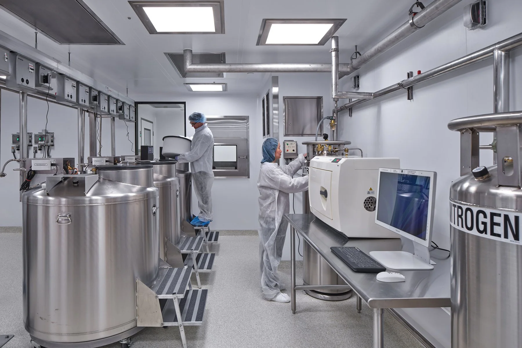
Cryogenic freezer storage. Photo courtesy of Todd Mason of Halkin Mason Photography
Ivan Atencio, EIT, project engineer at Affiliated Engineers, Inc., is co-author of this piece.
Liquid nitrogen (LN₂) is an essential utility in many pharmaceutical and biotechnology laboratories, supporting applications ranging from cryogenic sample storage and research to equipment cooling and specialized laboratory processes. Reliable LN₂ service can protect years of research and irreplaceable biological materials.
Despite its criticality, LN₂ is sometimes addressed only after major architectural and engineering decisions have been made. Planning for LN₂ storage, siting, distribution, monitoring, and emergency isolation early in design allows teams to define infrastructure requirements before they become costly change orders, redesigns, or schedule delays.
Selecting and siting LN₂ storage systems
Selecting an LN₂ storage strategy involves more than matching storage capacity to anticipated demand. The chosen approach must support laboratory processes and equipment while accounting for space, distribution, delivery, and maintenance requirements.
For laboratories with lower LN₂ usage, portable dewars may be the most cost-effective and flexible option compared with bulk or stationary systems. Facility design and operational planning must accommodate dewar movement and regular replacement, accounting for elevator access, clear travel paths, storage space, and changeover labor. Depending on the system configuration, actively connected dewars can boil off their contents in roughly a week, so backup duration should be calculated rather than assumed.
As consumption increases, reducing handling requirements and boil-off losses becomes more important, making bulk or microbulk storage more practical. As an initial planning guideline, a bulk tank may be sized so normal consumption results in a delivery approximately every four to six weeks. This is not a prescriptive requirement; the design team should establish capacity with the owner and supplier based on consumption, delivery logistics, site constraints, tank performance, and required reserve volume. Undersized tanks can result in frequent deliveries, while oversized tanks may increase evaporation losses. Where practical, vertical tanks are preferable because horizontal configurations can experience greater heat leak and require a larger site footprint.
Once the storage approach is established, the tank placement must balance distribution efficiency with broader site needs. Bulk tanks are typically positioned near the building to minimize costly vacuum-jacketed piping, but the closest location may not be the most suitable. Tank weight, seismic and structural requirements, clearances, security, and maintenance access can all constrain siting.
Beyond these considerations, life-safety and code requirements further influence tank placement. Tanks must not impede egress, and vent discharge should be appropriately separated from HVAC air intakes. The location must comply with applicable provisions of NFPA 55, adopted building and fire codes, and local requirements, while accounting for Compressed Gas Association (CGA) guidance and supplier criteria. Enclosed courtyards and indoor locations deserve particular scrutiny because mechanical ventilation may be necessary and some suppliers may not support tanks under these conditions.
Even when site and code requirements are satisfied, delivery access can ultimately determine whether the location is viable. A semi-truck must reach the fill connection and maneuver without compromising traffic, pedestrian circulation, or fire department access. Turning radii should be studied early, and the fill location should provide the operator a clear line of sight to the tank. Tank yards should restrict unauthorized access without impeding filling and maintenance.
Designing LN₂ distribution piping
Designing the path from bulk storage to each point of use is as important as selecting the storage system itself. The distribution system connects storage to the laboratory and can influence building layout well before piping is installed.
The distribution path begins outside the building at the bulk tank. Extending vacuum-jacketed piping as close as practical to the tank connection—and coordinating a vacuum-jacketed outlet and isolation valve—can reduce heat gain, LN₂ losses, and icing. Getting this configuration right requires close coordination between the bulk supplier and vacuum-jacketed piping manufacturer.
Inside the building, vacuum-jacketed piping presents different spatial requirements than conventional utilities. The vacuum jacket increases the overall pipe diameter, while cryogenic valves often use extended stems to reduce heat transfer and condensation at the operator. These characteristics require additional clearance in shafts, ceilings, corridors, and equipment service zones.
Distribution piping also requires careful routing and layout to support performance, constructability, and safety. Piping should follow the shortest practical path with minimal bends while maintaining the required slope—often 1%—to facilitate vapor movement. High points may require cryogenic vents routed to an appropriate exterior location. Seismic joints can add complexity because vacuum-jacketed piping cannot always accommodate movement like conventional utility piping. Identifying these conditions before fabrication reduces the likelihood of costly field modifications.
At equipment connection points, piping must be properly supported, cryogenic storage equipment anchored, and flexible hose lengths coordinated to avoid unintended traps. Where LN₂ is manually dispensed into open containers, such as cryoshipper filling stations, the layout should account for working clearance, ventilation, and personnel protection because of increased spill and release potential.
Distribution piping should be planned around how the laboratory may change over time. Rather than simply oversizing piping, teams can establish strategic expansion points using block-and-bleed isolation, cryogenic venting, and appropriately located bayonet fittings. Keeping these provisions accessible can allow future connections while reducing shutdowns and modifications to an operating laboratory.
Constructability also warrants attention throughout design and fabrication. Vacuum-jacketed piping is difficult to modify in the field because of its welded construction and vacuum insulation. Rerouted or damaged pipe spools may require specialized fabrication, bake-out, and vacuum testing before installation. Detailed shop drawings coordinated among the designer, contractor, piping manufacturer, and bulk supplier can identify conflicts before fabrication and avoid additional testing, shutdowns, and schedule impacts.
Layered safeguards for LN₂ systems
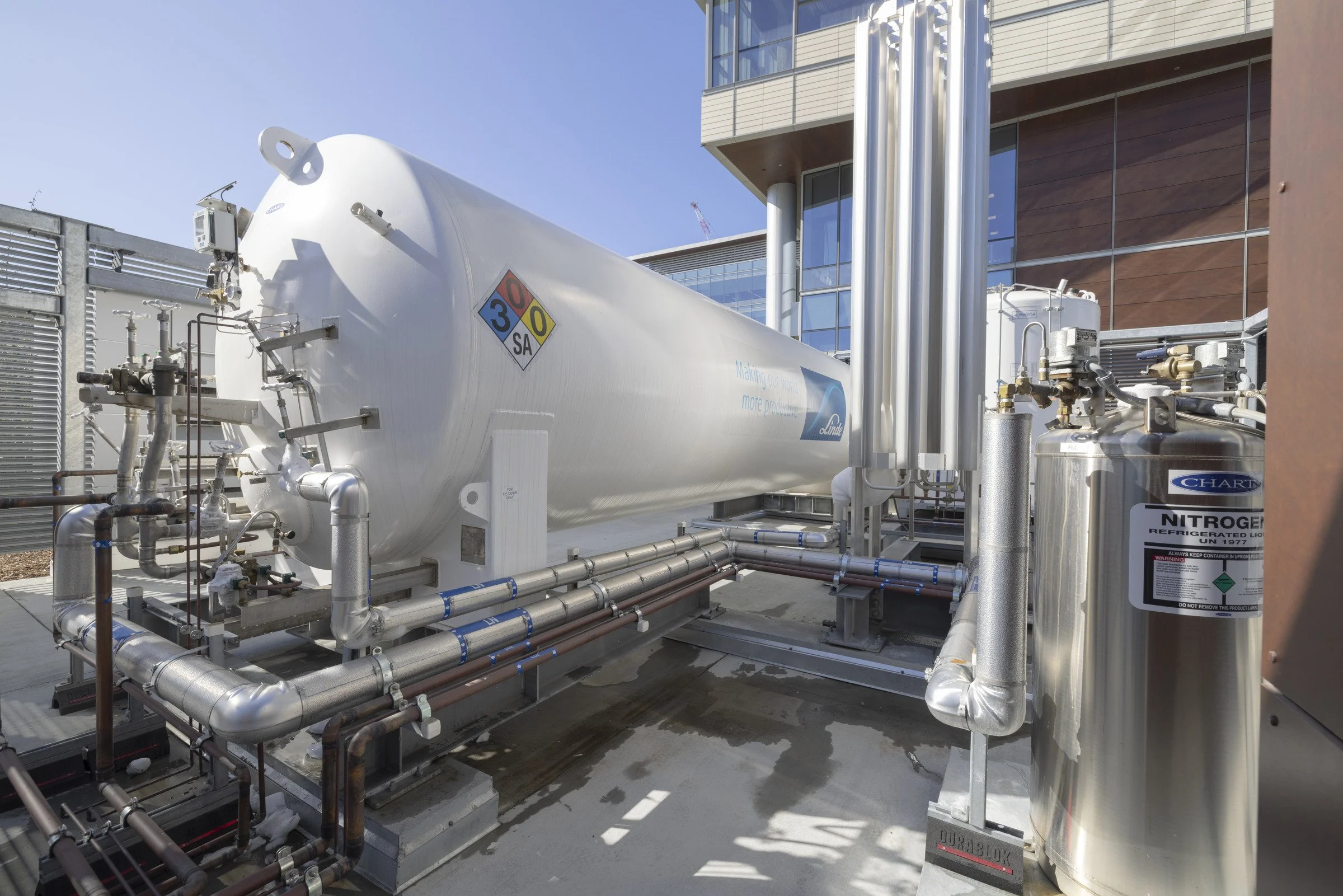
Combined liquid and gaseous nitrogen system with horizontal tank. Photo courtesy of Jasper Sanidad Photography
Nitrogen vapor from an uncontrolled LN2 release can displace oxygen, creating an asphyxiation hazard. Managing this risk requires multiple, independent layers of protection rather than reliance on a single sensor, valve, ventilation system, or operating procedure.
Codes and standards establish a safety baseline. Although LN₂ use alone does not trigger OSHA Process Safety Management under 29 CFR 1910.119, laboratories must still consider applicable OSHA requirements, NFPA 55, CGA guidance, adopted building and fire codes, local provisions, and owner EH&S standards. Because these requirements cannot address every laboratory process or equipment configuration, an early formal hazard assessment should shape the design. Where appropriate, HAZOP-style reviews can evaluate credible release scenarios, gas-release calculations, instrumentation failures, alarm responses, and emergency procedures.
The findings should guide an integrated monitoring, ventilation, and isolation strategy. Oxygen sensor placement must account for likely release points, room geometry, ventilation patterns, and occupied zones. Because nitrogen released from LN₂ is initially extremely cold, low-wall exhaust may be appropriate where cold vapor could accumulate before warming and mixing with room air.
When an oxygen-deficient condition is detected, the monitoring system can initiate multiple independent protective responses. Depending on the risk assessment, these may include audible and visible alarms, increased exhaust, automatic closure of an LN₂ isolation valve, and notification through the building automation system. Manual emergency stops provide another means of isolation and should be positioned where personnel can safely operate them without entering the affected room.
LN2 safeguards must also remain reliable and maintainable. Critical monitoring, alarms, isolation valves, and controls may require emergency or UPS power. Alarm and sensor data can integrate into a building automation system or historian to support incident response and troubleshooting. Valves, sensors, and emergency controls should remain accessible for routine inspection, testing, and calibration.
A January 2021 incident at the Foundation Food Group facility in Gainesville, GA demonstrated the importance of independent layers of protection. A failure in an immersion freezer's level-control system allowed LN₂ to overflow and create an oxygen-deficient atmosphere, killing six workers and seriously injuring four others. The US Chemical Safety and Hazard Investigation Board identified the level-control system's single point of failure and the absence of atmospheric monitoring and alarms among the key safety issues.
The incident reinforces two principles applicable to laboratory LN₂ systems. Safety-critical functions should not rely on the same instrumentation used for normal process control when doing so creates a single point of failure. Oxygen monitoring should also be incorporated where the hazard assessment determines that a credible release could create a dangerous atmosphere. Combined with ventilation, isolation, alarms, emergency shutdowns, and operating procedures, these measures provide independent layers so one failure does not defeat the entire protection strategy.
Treat LN₂ as facility infrastructure

Ivan Atencio, EIT, co-author of this piece, is a project engineer at Affiliated Engineers, Inc., providing process engineering and consulting services for the Bay Area's premier biotechnology companies. He is well-versed in cryogenic distribution and instrumentation, high-purity water systems, small and large molecular processing, and sterile processing.
LN₂ should be planned as facility infrastructure rather than as an equipment connection addressed late in design. Early planning preserves viable storage locations, efficient distribution routes, appropriate safeguards, and future expansion opportunities before options become constrained by the building and site.
Bringing laboratory users, EH&S representatives, designers, facility operators, specialty piping manufacturers, bulk suppliers, and the construction team into the process at the appropriate stages supports deliberate decision-making. The result is an LN₂ system designed not only to meet today's demand, but to remain safe, maintainable, and adaptable as the laboratory and its research needs evolve.