
Decarbonizing Labs Through Thermal Energy Networks
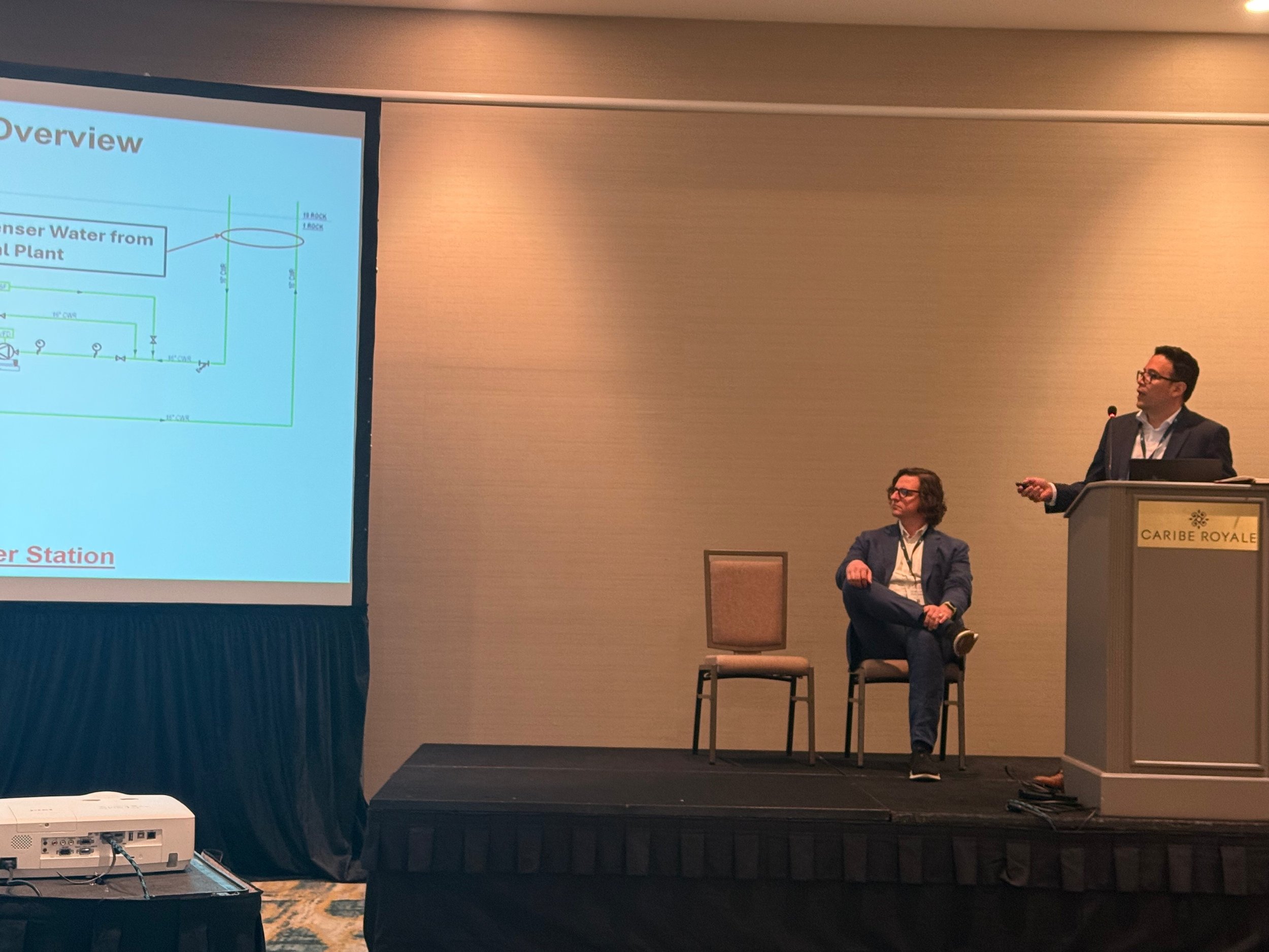
At the 2026 Lab Design Conference in Orlando, FL, Charlie Marino and Victor Sanchez of WSP presented how Utility Thermal Energy Networks can help campuses and districts decarbonize laboratories through shared energy infrastructure and heat recovery.
As higher education institutions, healthcare facilities, and research campuses face mounting pressure to hit aggressive greenhouse gas (GHG) reduction targets, facility managers and engineers are hitting a wall with existing infrastructure. Laboratory buildings are notoriously difficult to decarbonize. Their intense energy requirements, high simultaneous heating and cooling demands, limited roof area for air-source equipment, and strained electrical distribution make building-by-building electrification a daunting—and often cost-prohibitive—endeavor.
At the 2026 Lab Design Conference in Orlando, FL, Charlie Marino, partner and co-director of the energy + performance team at WSP, and Victor Sanchez, assistant vice president at WSP, presented a compelling alternative: Utility Thermal Energy Networks (UTENs). Rather than forcing every laboratory to bear the full burden of on-site electrification, campuses and urban districts can leverage thermal energy networks to share energy, optimize heat recovery, and outsource infrastructure challenges. They reviewed this in their Lab Design Conference session, “Decarbonizing Labs Through Thermal Energy Networks.”
The evolution of district energy: moving toward Gen 5
To understand the promise of thermal energy networks, Marino outlined the historical progression of district energy systems:
| Generation | Timeline | Primary Fuel / Medium | Key Characteristics |
|---|---|---|---|
| Gen 1 & 2 | Early 1900s | Coal, Fuel Oil / Steam, High-Pressure Hot Water | Reliable, but suffers from high thermal losses and heavy GHG emissions. |
| Gen 3 | 1980s | Natural Gas / Cogeneration (CHP) | Improved efficiency via combined heat and power, but still relies on high-temp distribution. |
| Gen 4 | Past 20–30 Years | Low-Temp Hot Water, Central Geothermal | Dedicated 4-pipe distribution; direct low-temp hot water delivery. |
| Gen 5 (UTEN) | Present / Emerging | Decentralized Ambient Loop (50°F–90°F) | Highly flexible "thermal highway"; uses decentralized water-source heat pumps. |
In a Generation 5 (Gen 5) ambient loop configuration, water is circulated at near-ambient temperatures 50 to 90 degrees F. Individual buildings use water-source heat pumps to extract heat for space heating or reject heat for cooling.
Gen 5 systems act like a thermal highway, Marino explained. “You're utilizing an ambient loop that can inject and reject heat based upon the conditions of the building.” This offers the flexibility to plug in low-carbon solutions like wastewater heat recovery, data centers, or geothermal borefields throughout the distribution.
Why thermal networks and labs are a perfect match
Laboratory buildings present unique decarbonization hurdles, but they also possess features that make them ideal nodes in a thermal energy network.
1. Overcoming on-site physical and electrical constraints
Retrofitting an existing lab with air-source heat pumps often fails due to a lack of available roof space and the massive electrical service upgrades required to support peak heating loads. By shifting to a water-source heat pump strategy tied to a central ambient loop, campuses can drastically minimize electrical capacity increases inside individual lab buildings while preserving mechanical room and rooftop footprints.
2. Labs as thermal assets
While labs consume significant amounts of energy, they also generate vast quantities of waste heat through 24/7 cooling loads, process equipment, and continuous exhaust. In a Gen 5 system, a laboratory’s rejected heat isn't lost through a cooling tower—it is harvested and pushed into the network loop to heat adjacent facilities, such as dormitories, multi-family housing, or administrative offices.
3. Future-ready flexibility
“You don't know what's going to happen with research and development in the heat pump space over the next five years,” Marino noted, referencing rapid advancements in high-temperature and steam-generating heat pumps. An ambient thermal loop allows institutions to upgrade heat generation technologies over time without overhauling the underlying distribution infrastructure.
Case study: harvesting waste heat at Rockefeller Center
To demonstrate how low-carbon thermal networks operate in dense, real-world environments, Sanchez walked Lab Design Conference attendees through WSP’s mega-retrofit project at Rockefeller Center in Midtown Manhattan—a project governed under New York State’s Utility Thermal Energy Network Jobs Act (UTENJA).
Rockefeller Center spans eight million square feet and historically relied on district steam (Gen 1) for space heating. However, the complex operates year-round central cooling plants—including refrigeration for its iconic ice rink—resulting in massive heat rejection through its cooling towers.
Rockefeller Center Heat Recovery Flow
Engineering challenges and creative solutions
Reclaiming rejected heat: WSP designed an Energy Transfer Station in a former loading dock area beneath 30 Rockefeller Plaza. Instead of dumping condenser water heat out of cooling towers, a heat exchanger diverts that thermal energy into an electric heat pump loop, boosting water temperatures up to 130 degrees F for space heating in adjacent buildings.
Displacing fossil fuel boilers: The thermal energy recovered from the central plant provides approximately $30,200. “Picture you have 600 homes, and they're 1,500 square feet each. With this heat, we can heat heat them all in in cold climates. So that's how how big this project really is,” said Sanchez.
Subterranean spatial puzzles: Running four 10-inch distribution lines across Sixth Avenue to customer buildings like 1221 Avenue of the Americas proved impossible underground due to subway lines, high-pressure steam pipes, and dense utility corridors. WSP pivoted by routing the distribution piping through public subway concourse levels. To maintain required headrooms, engineers manifolded the main 10-inch lines into four sets of 6-inch pipes before re-combining them on the customer side.
Subterranean Sixth Avenue Crossing
Key takeaways for lab facility designers
For institutions considering thermal energy networks or district-scale decarbonization, the speakers highlighted critical planning guidelines:
Prioritize hydronic upgrades: Buildings with low-temperature hot water distribution systems (120 degrees F or lower) are prime candidates for thermal networks. Designing lab air handling units and perimeter induction loops for lower heating fluid temperatures today ensures seamless integration with future heat pump networks.
Size for peak vs. mass volume: Designing thermal networks to meet 80 percent to 90 percent of annual heating energy needs—while retaining existing steam or dual-fuel infrastructure for extreme peak events—drastically lowers initial capital costs while delivering significant carbon reductions.
Selectivity in thermal matching: Thermal networks require balance. When master-planning a campus network, balance lab exhaust/condenser heat rejection with consistent thermal sinks, such as domestic hot water loads or surrounding residential buildings.
Looking to bring low-carbon innovation to your own facilities? The Lab Design Conference returns May 10-13, 2027, in Dallas, TX. Join leading engineers, architects, and lab planners as they share real-world case studies, emerging energy trends, and practical strategies for designing and retrofitting the next generation of high-performance research laboratories.